Complexity explained simply
We use functional graphics to explain the functional and operating principles of our products. As these are sometimes very complex and not immediately easy to understand by everyone, the graphics are always limited to the essentials.
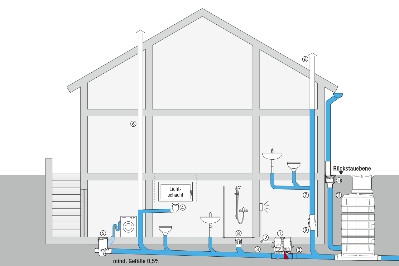
Schematic diagrams
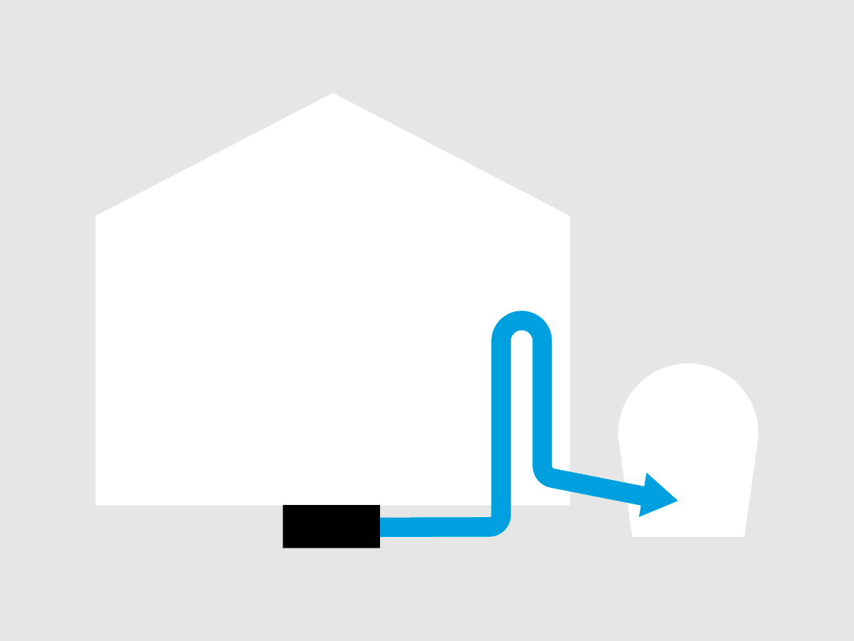
KESSEL products and their application are explained schematically to the customer. Schematic diagrams are used here to provide a simple and comprehensible explanation. The schematic diagrams are presented in abstract form and do not show any technical details. They are used for marketing and training purposes and do not claim to be a detailed illustration of reality. They are always accompanied by an explanatory text.
Three different levels of complexity are shown below as an aid in the preparation of new schematic diagrams.

The structure - step-by-step
All graphics are based on the basic KESSEL design guidelines in terms of colour, shape and typography. In order to ensure a uniform illustration, the most important steps for creating schematic diagrams are listed below. If you want to create a schematic diagram yourself, then use the template file: It contains all the design elements that you need.

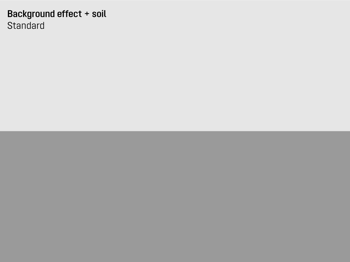
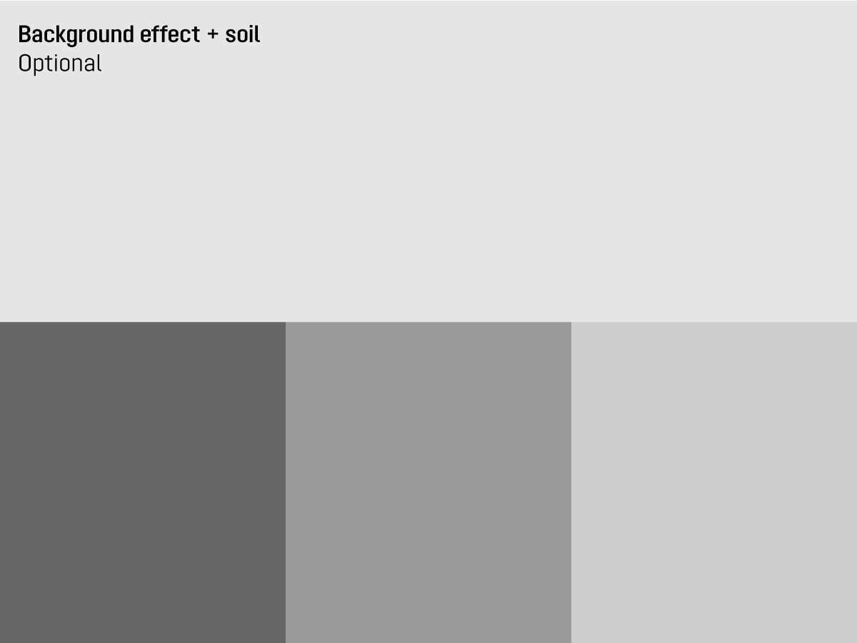
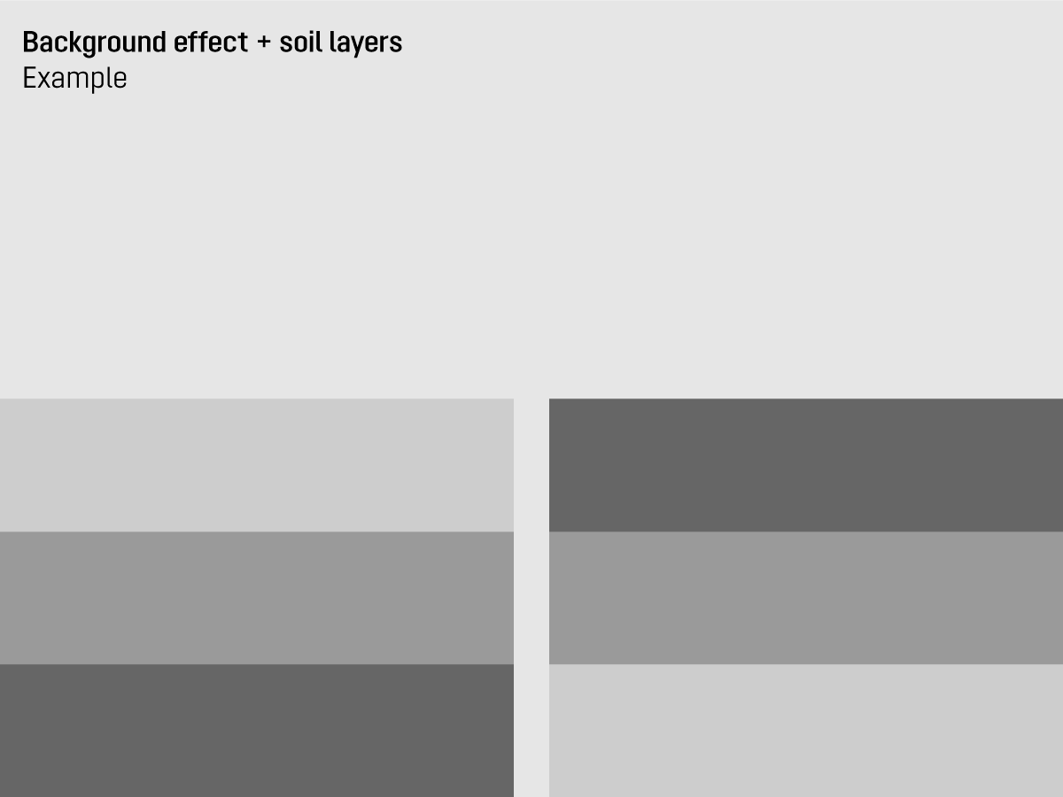
Each schematic diagram uses a background effect to give structure to the layout. The following standard values are defined for this:
Background effect/sky: grey background (#E5E5E5)
Soil: grey 2 (#999999)
Soil layers: grey 1, 2, 3 and grey background
If necessary, the grey tones can vary within the specified colour tones.

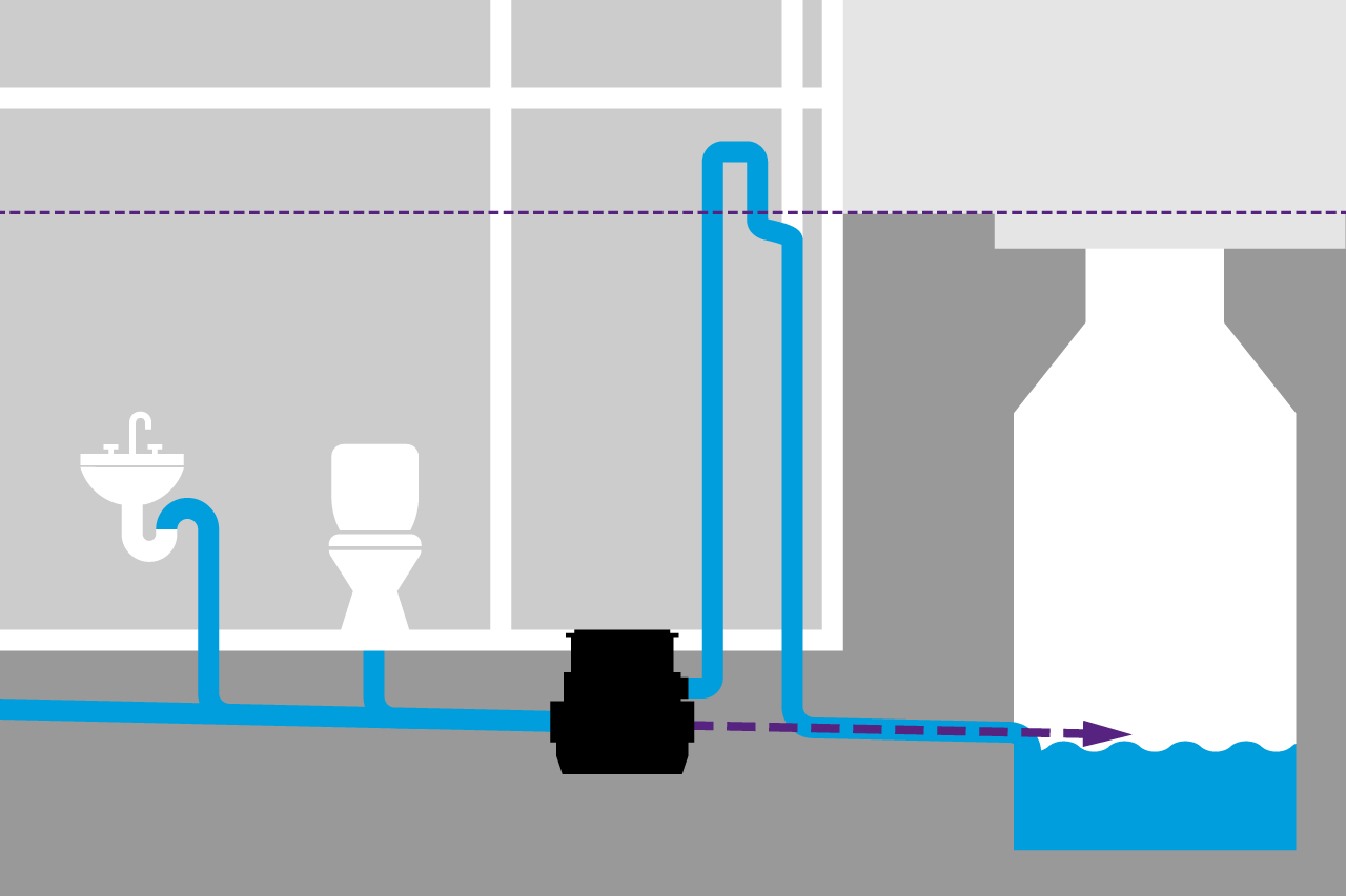
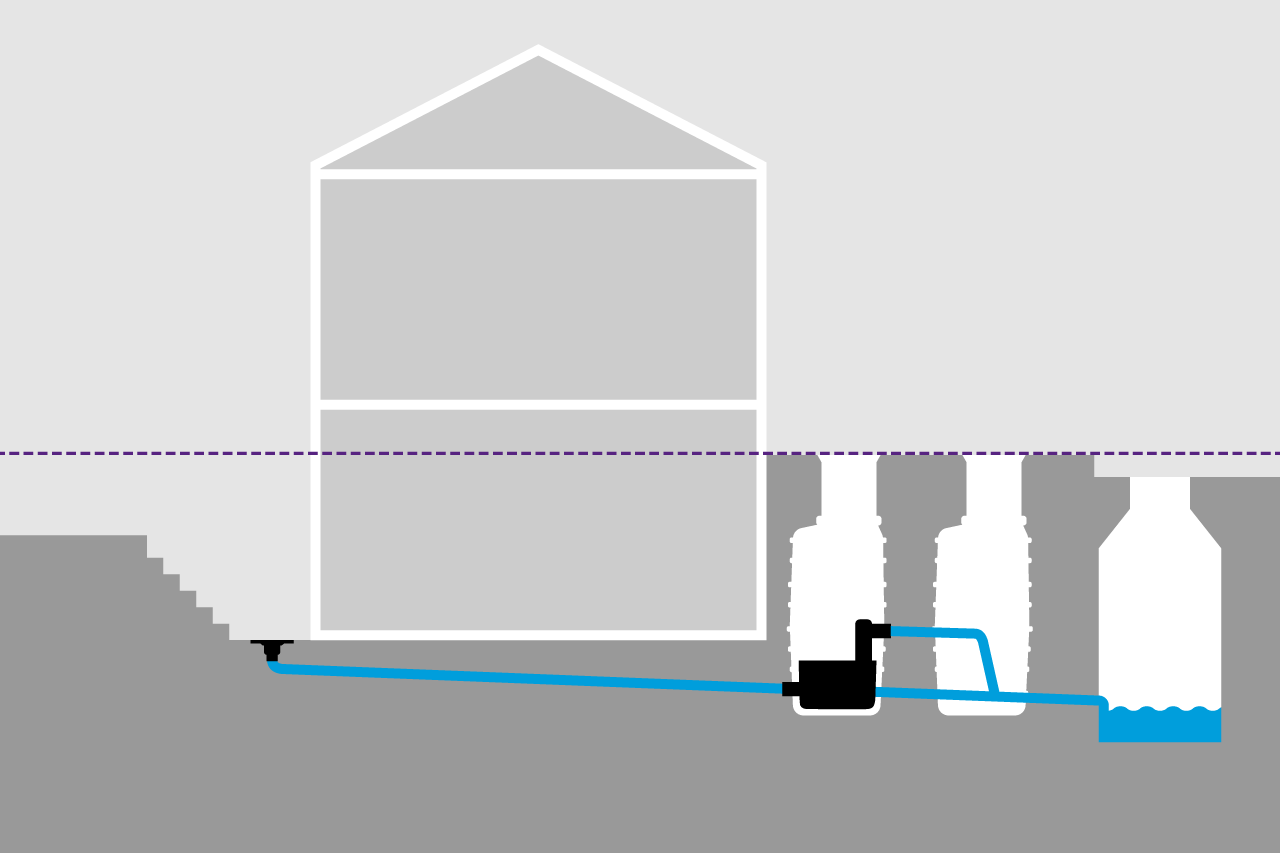
There are two illustration formats for buildings and spaces: simplified and complex. The choice depends on the content and detail level in the graphic.
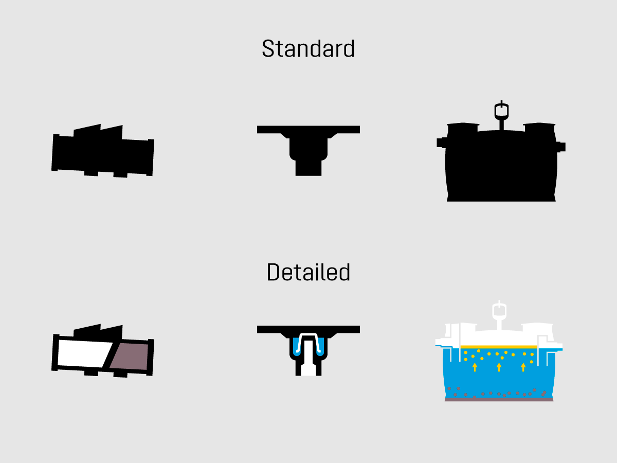
A distinction is made between two types of product illustration: standard and detailed.
Standard product illustrations are simplified illustrations that are based on the proportions of the real products.
In contrast, detailed product diagrams show the interior of the products and convey individual functions/features of a product. These illustrations can be supplemented by explanatory elements.
Refer also to:

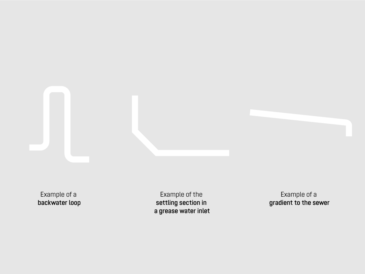
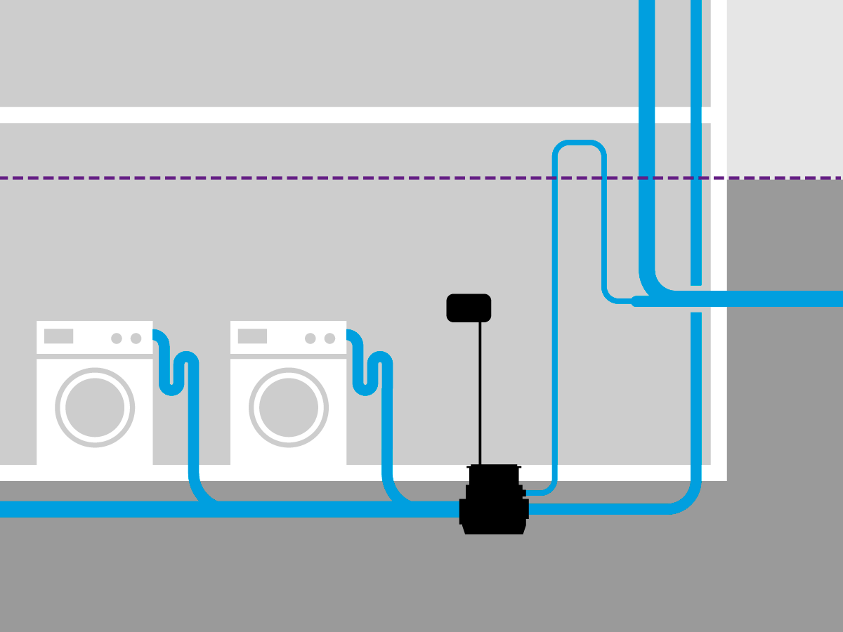
The contour thickness and corner radii of the pipes must be selected depending on the detail level in the respective graphic.
A distinction is made between empty (white) and full pipes (colour coding according to the solids and liquids section).
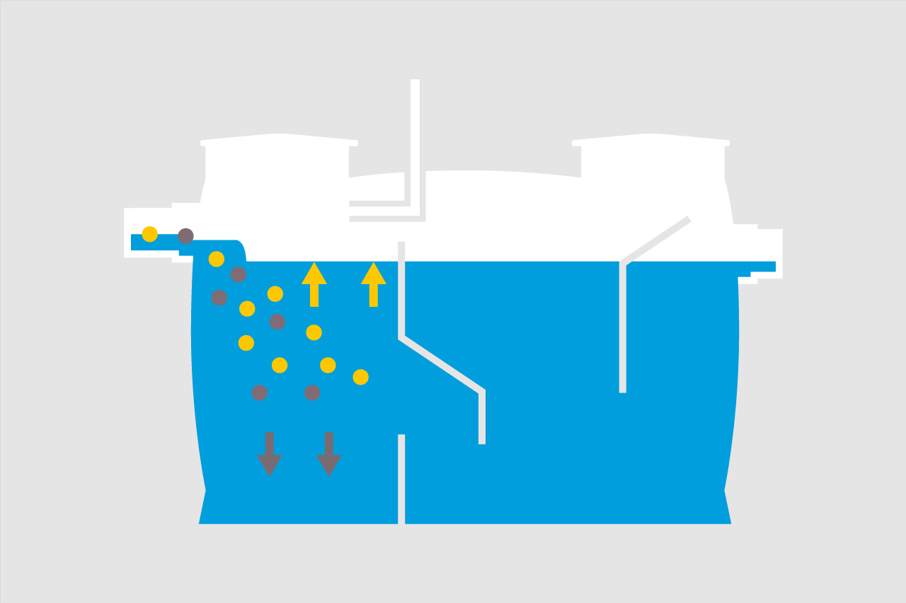
Furthermore, fundamental, product-specific circumstances must be taken into account. Examples of this may be:
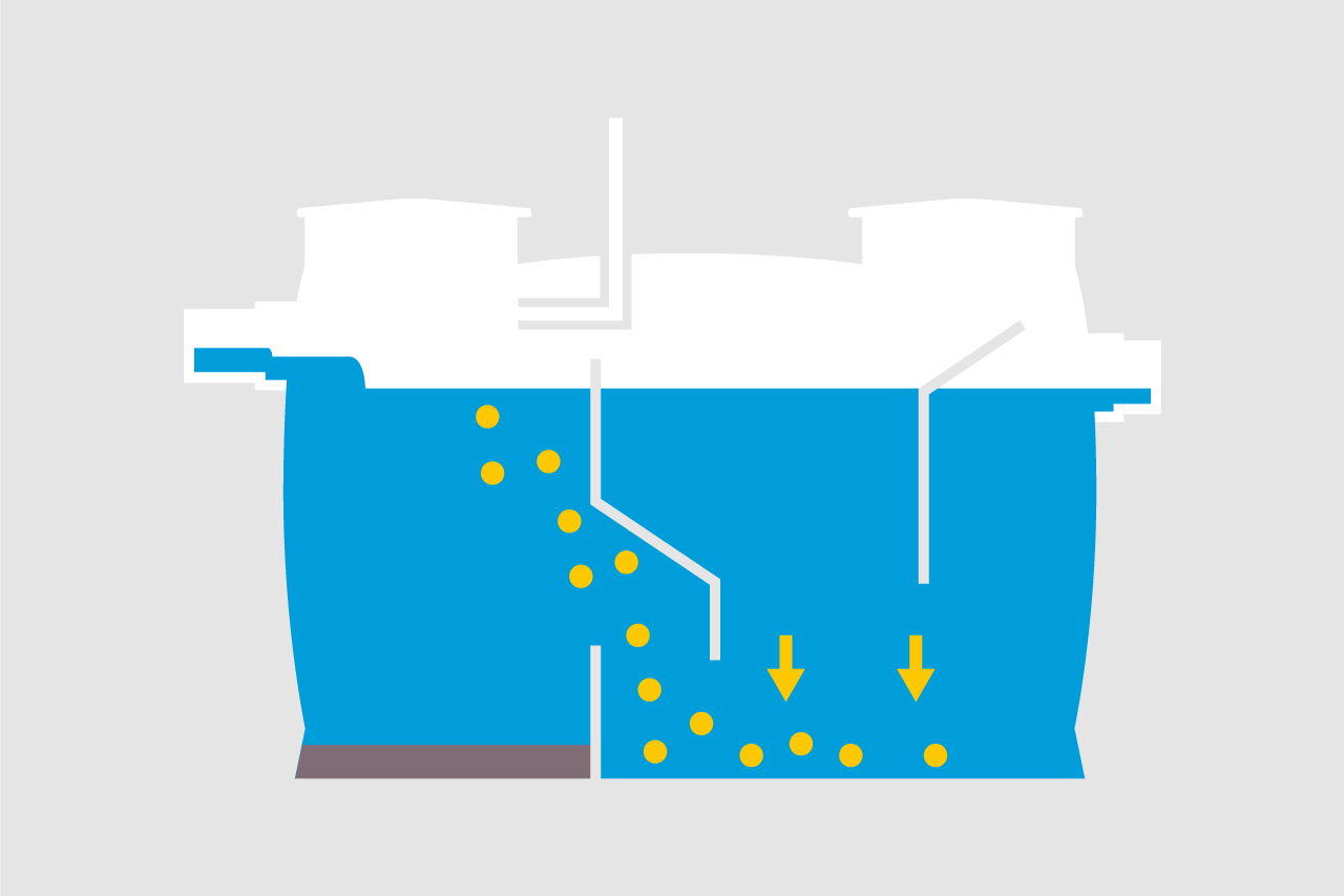
– Settling section in a grease separator
– Backwater loop above the backwater level
– Gradient to the sewer

The illustration of sanitary products, electrical appliances and other elements is based on the basic styling of icons and infographics. A large selection of elements can be found in the template file.
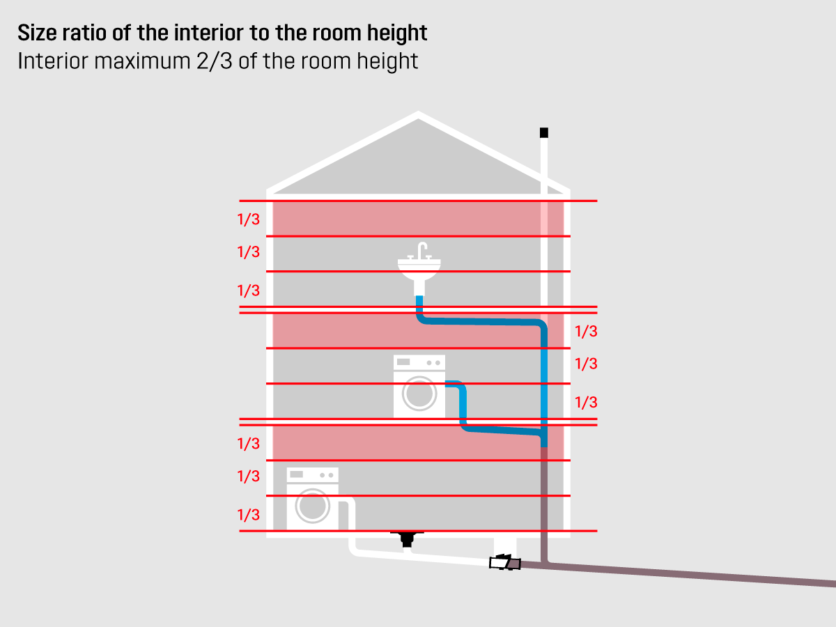
Height ratio: The maximum height of products or equipment in the room is 2/3 of the room height.
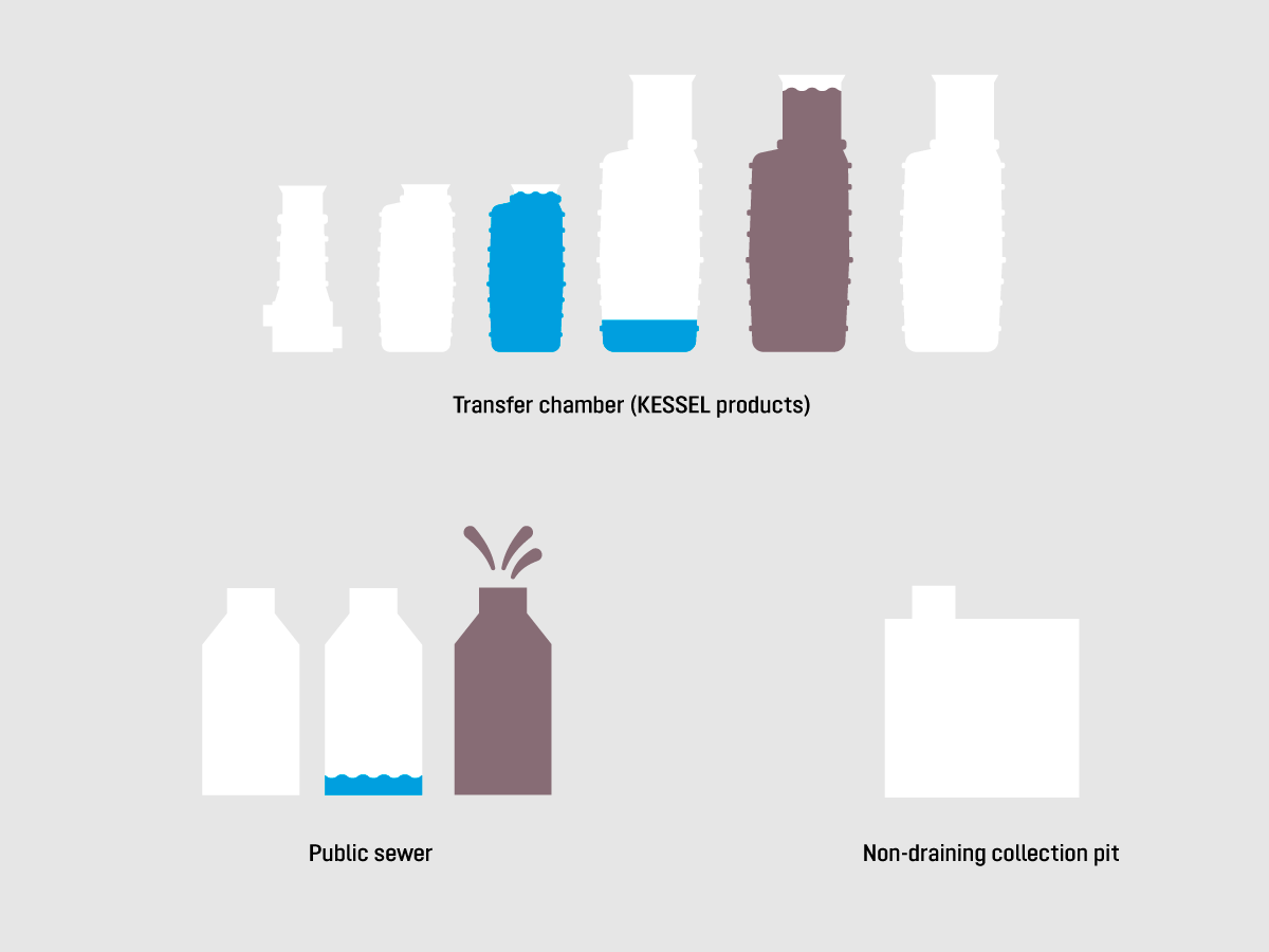
Predefined elements are available in the design module for the illustration of transfer chambers, inspection chambers and the connection to the sewer system.
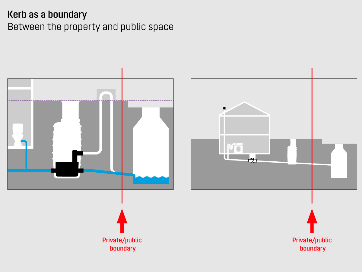
As a general rule: The kerb represents the boundary between the property and public space.


The colour coding of solids and liquids is defined in the design module.
Example:
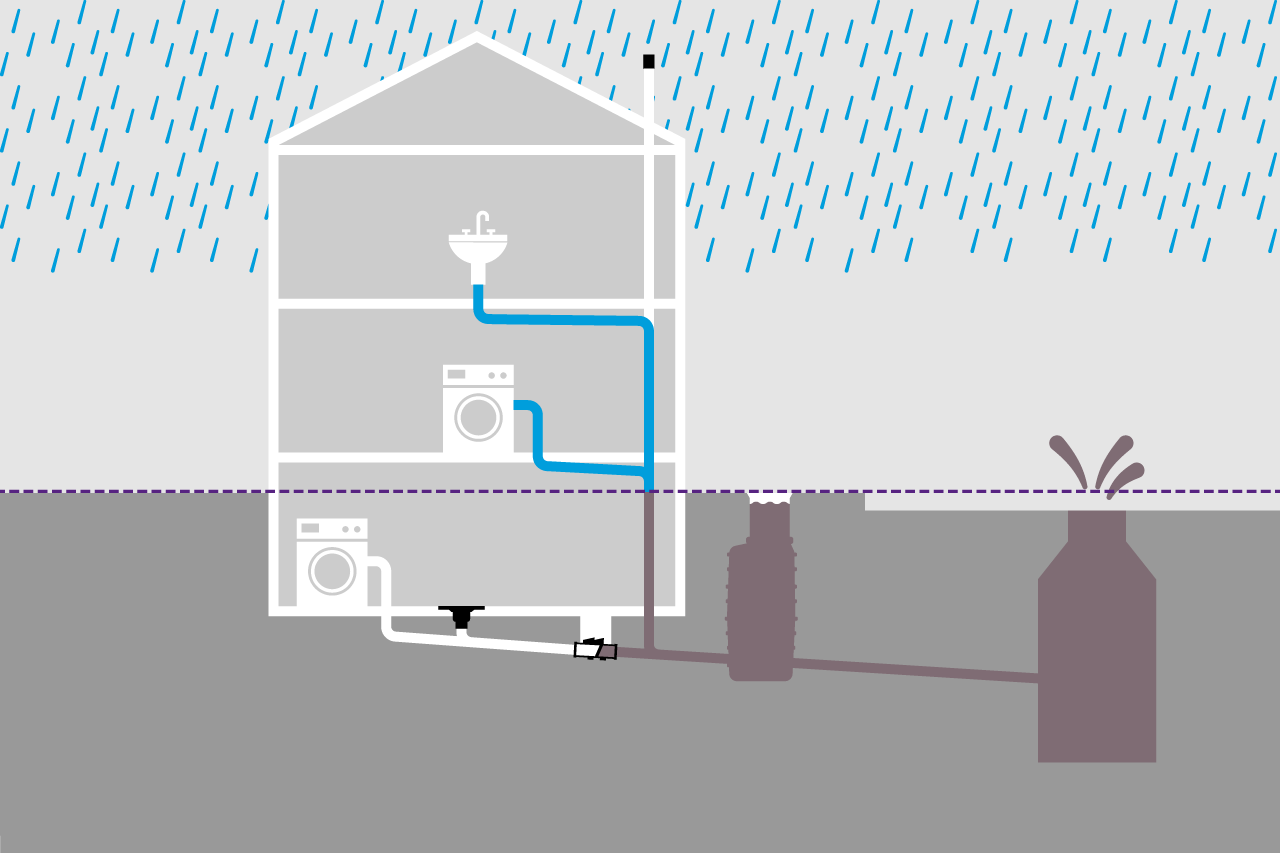
Rainwater and grey water: blue (#009EDC),
Black water and backflow: brown (#7F6C74)
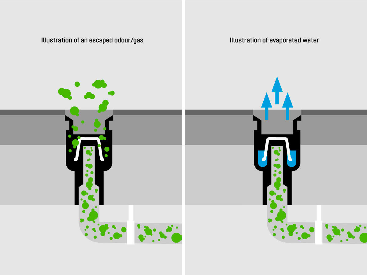
The complete list of all the existing colour coding can be found in the template file. It also contains sample illustrations for floating solids or settling solids as well as for odours and gases.
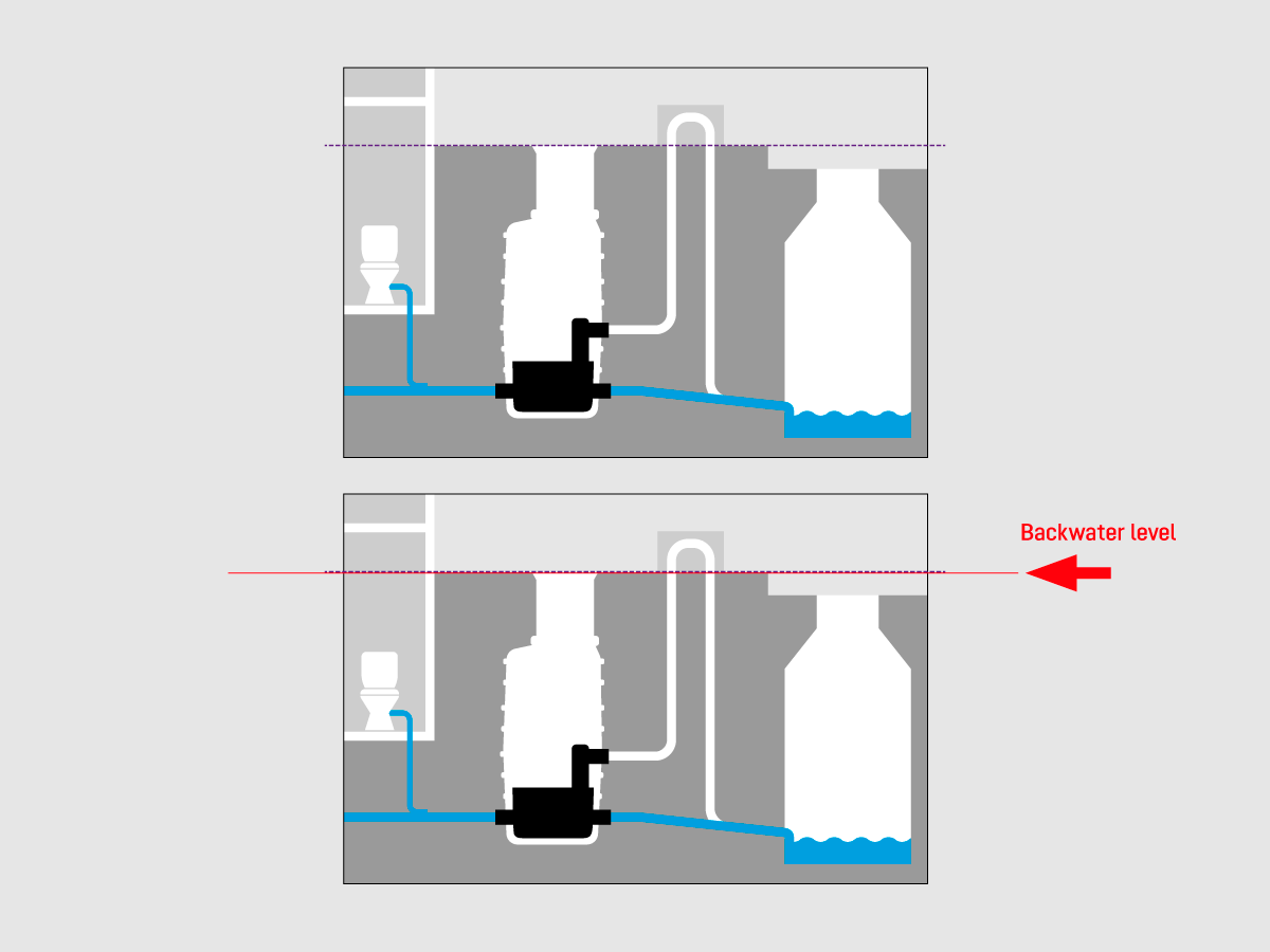

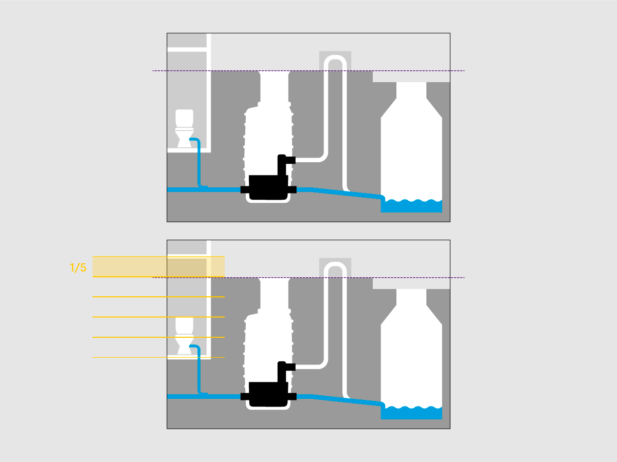

A binding template and the following application rules are available for uniform illustration of the backwater level:
Position of the backwater level: The backwater level is always on the upper edge of the kerb, NOT on the upper edge of the road.
Height ratio: The standard height ratio of the basement/ground floor level to the backwater level is 4/5 of the room height of the basement.

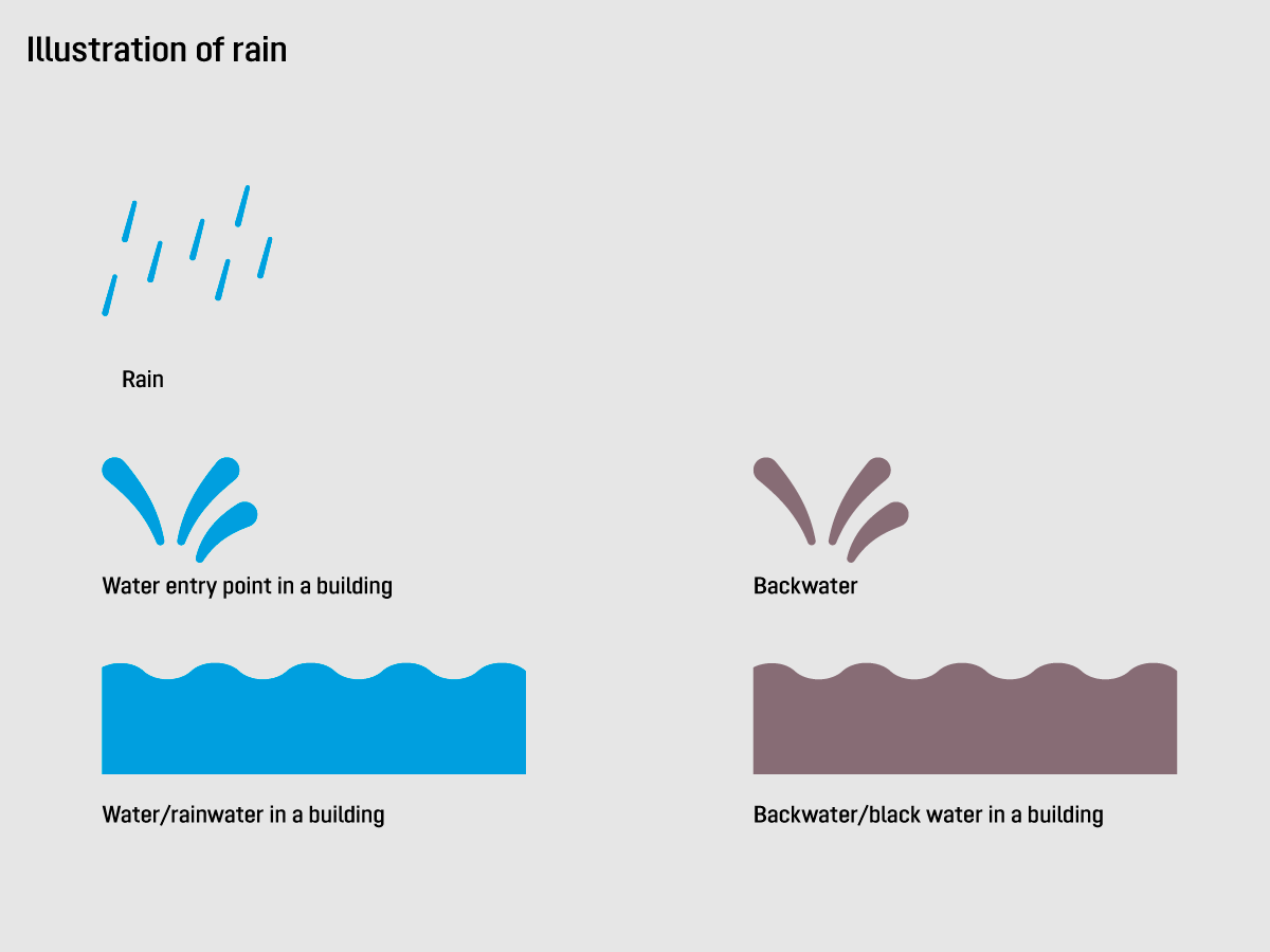
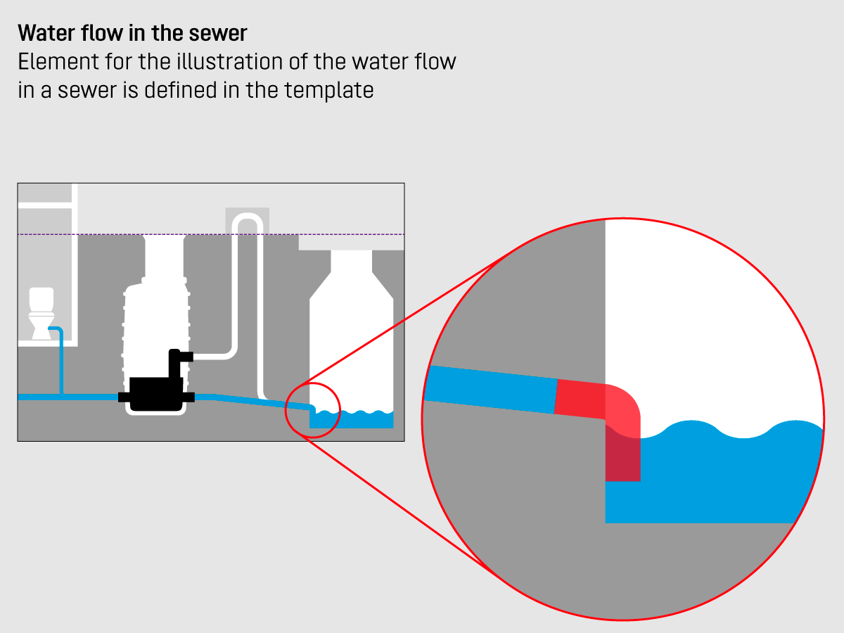
There are specific template elements to be used for the illustration of rain, water entering a property and backwater in a building.
Icons and arrows can be used to explain complex correlations. Templates for this can be found in the design module.
Text elements in graphics should not be used for reasons of multilingualism.
In addition, it is possible to highlight individual elements with secondary colours.
Best practice


Don’ts


Not found what you are looking for?
Although the KESSEL brand portal is constantly growing, not all information is gathered here. If you have any questions about the correct implementation of standard graphics, layer diagrams or technical drawings, please do not hesitate to send us an e-mail.